


Click to view a full size picture (opens in a new tab)

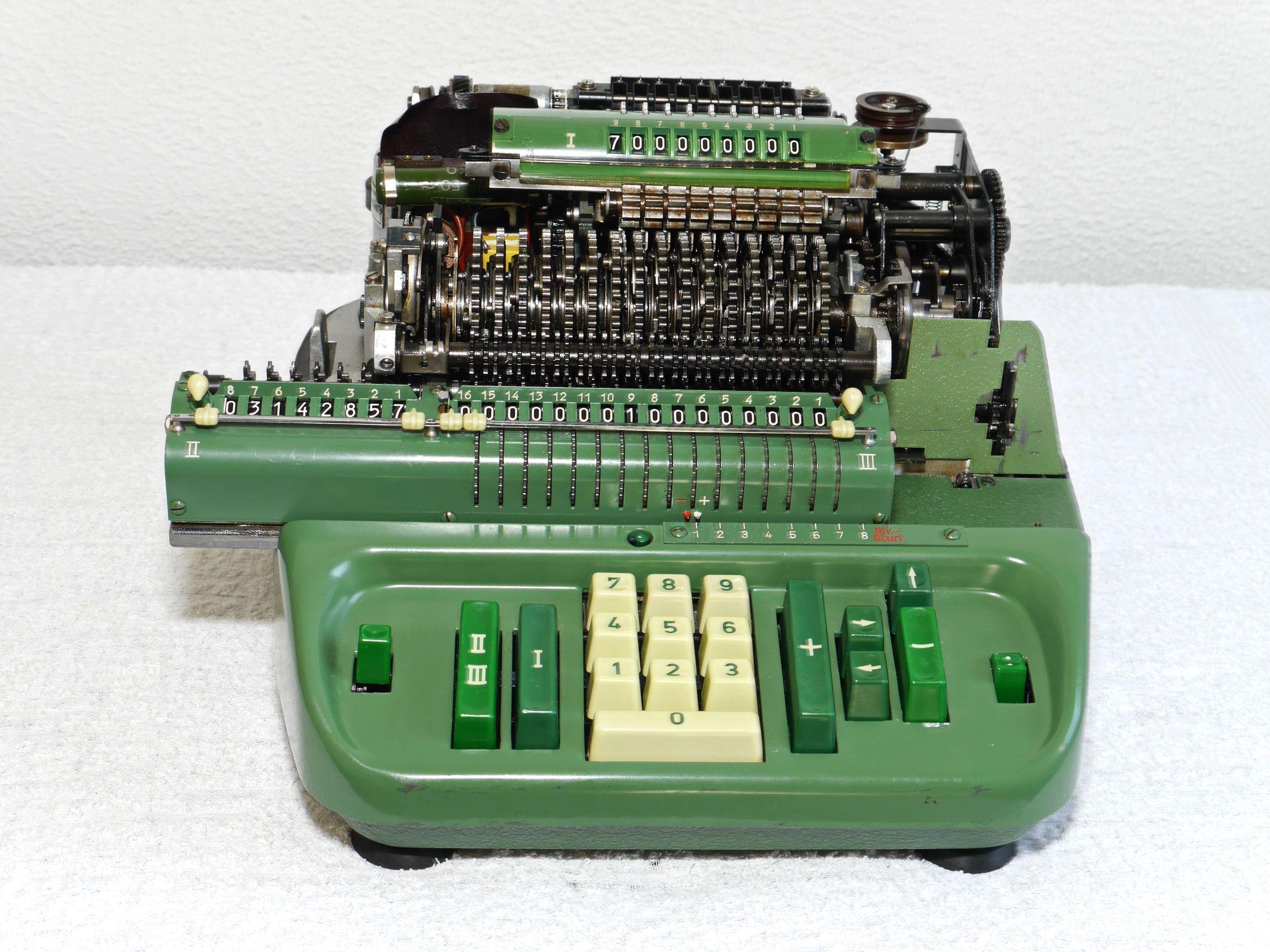
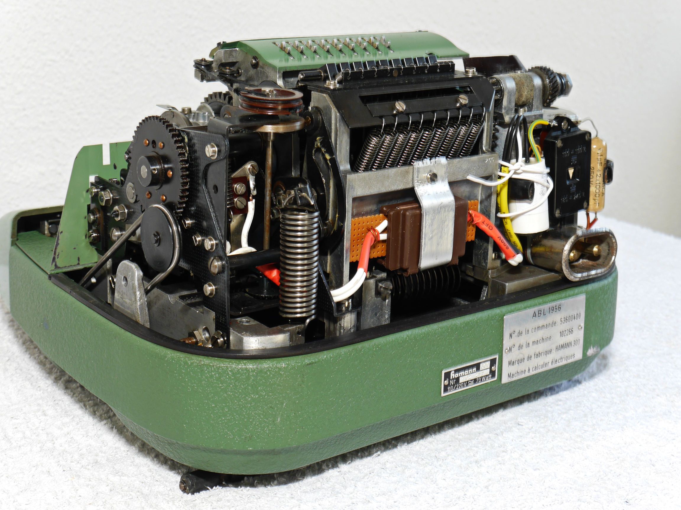
When I first received this calculator, it was in reasonably good condition. It could add and subtract, but the carriage transport wasn’t functioning properly, and division didn’t work at all. With this Hamann, I discovered that removing the carriage is quite simple—as long as the machine is functioning properly. If it’s not, removing the carriage can be quite a challenge. However, doing so is necessary to access certain components that may be preventing the machine from working correctly.
Carriage removal:
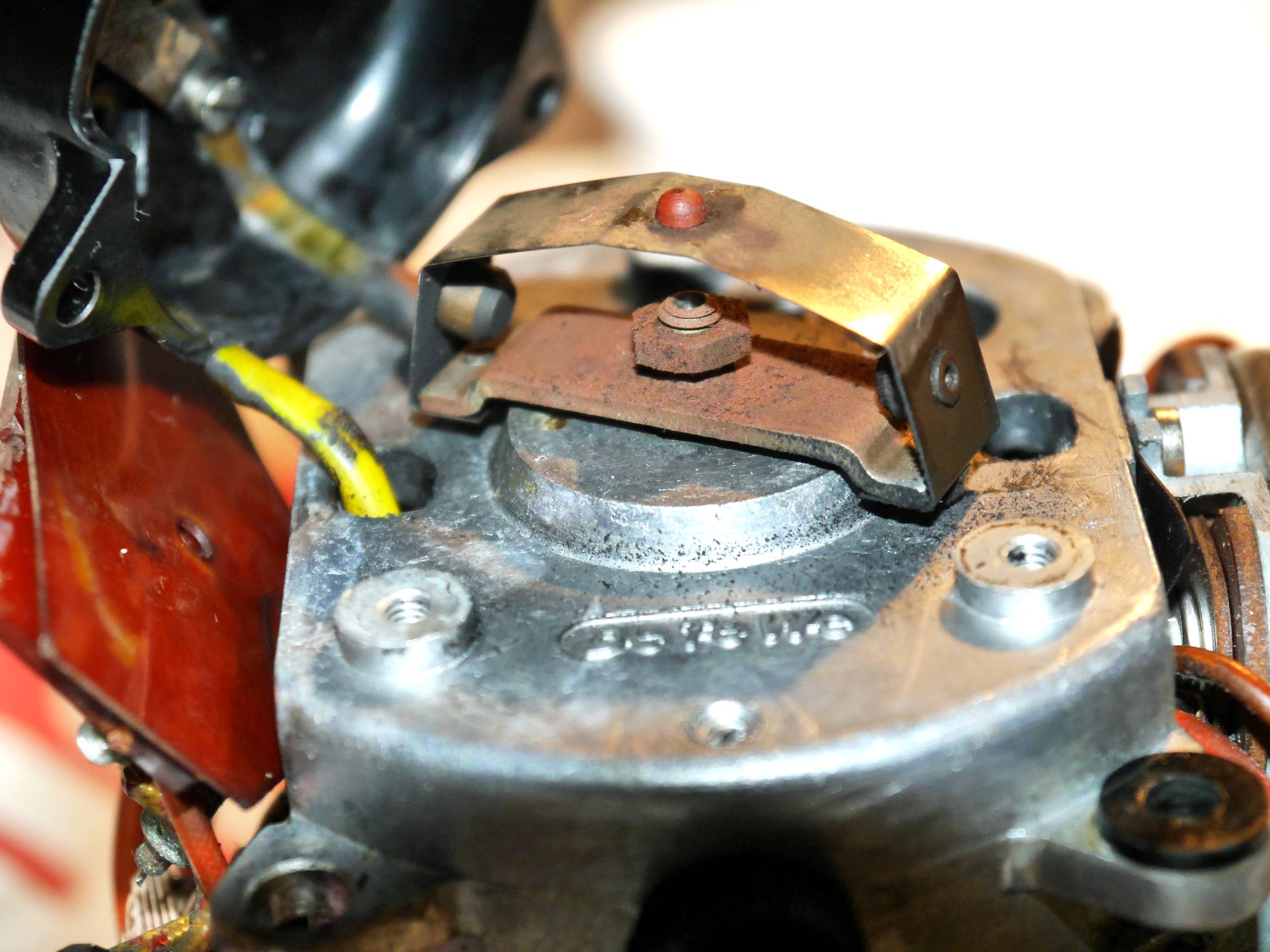
When the machine is in its usual position, at the lower-right of the carriage, you’ll find a small steel piece attached with two screws (see photo A). Once this is removed, the carriage should easily slide out. To remove it, move the carriage all the way to the right. Afterward, the carriage can be moved left until it disengages and can be taken out. It's easiest to manually operate the carriage by turning the small wheel, which is driven by a long steel spring. At the same time, press the right-tab key, followed by the left-tab key. If the machine is functioning properly, using motor power is also an option.
If the carriage seems to be stuck, here’s something to check:
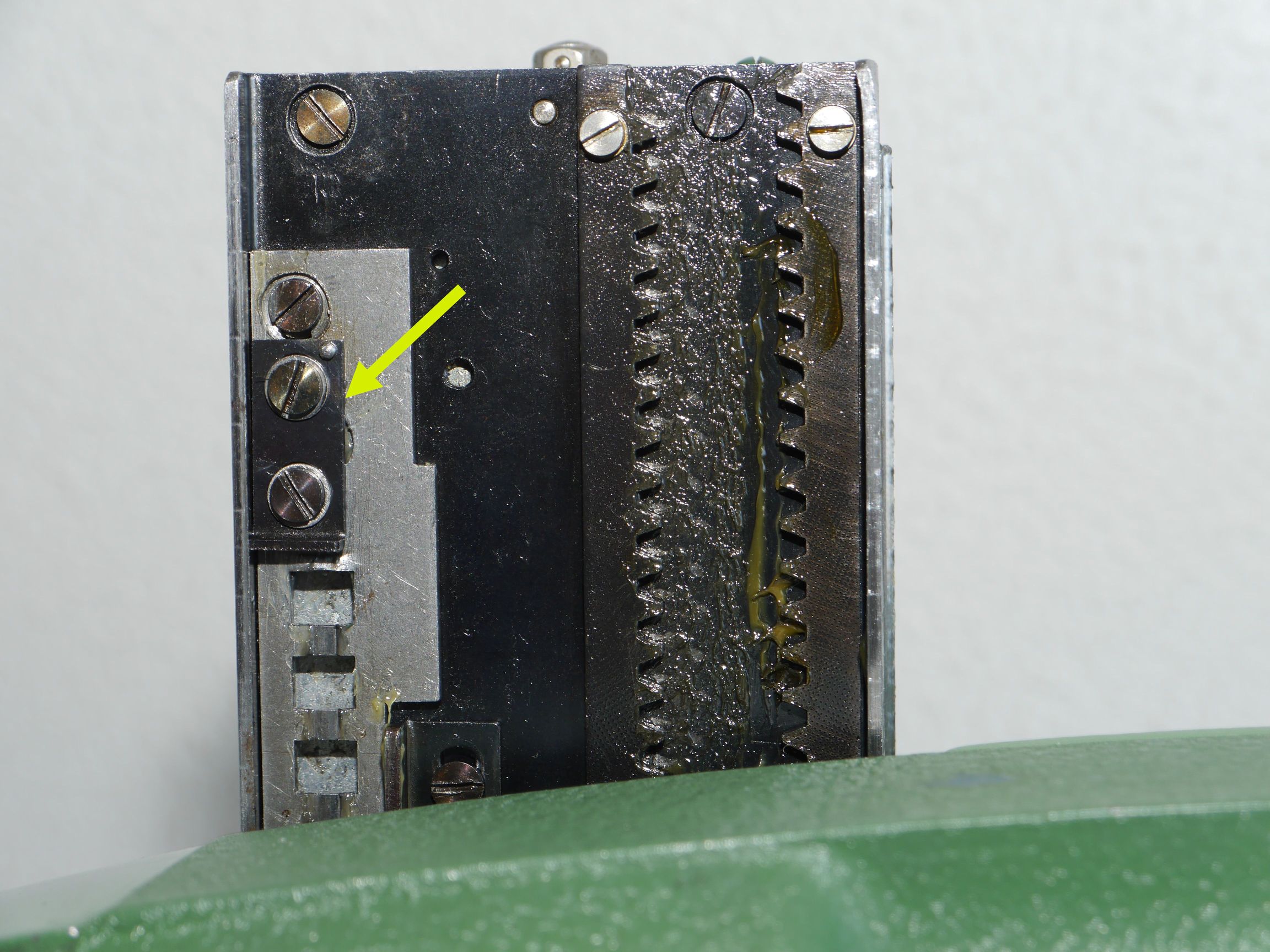
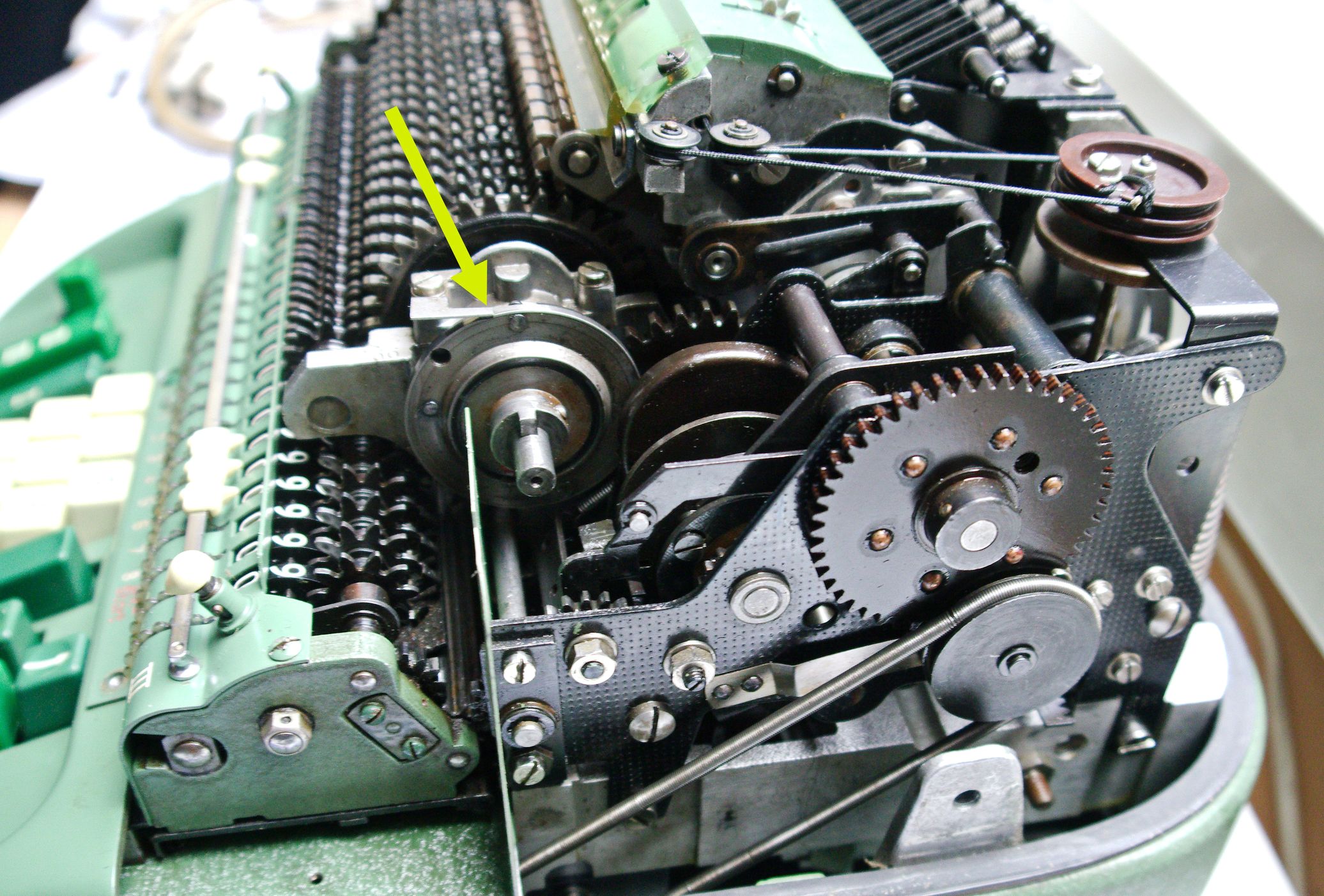
Has the main register (Reg I) completed its 360-degree rotation? If not, the carriage will be securely held by two mechanisms. One is visible in photo C, marked by the yellow arrow, while the other is underneath the carriage and can only be seen once the carriage is removed.
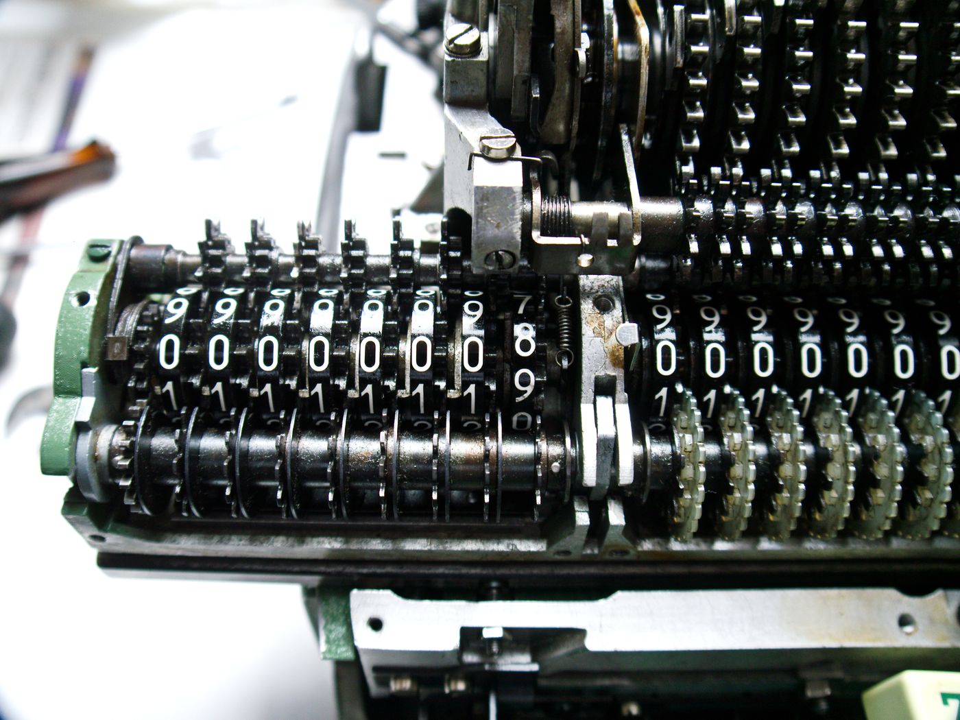
A common reason for Reg I not reaching its 0-position (see photo D) is a sluggish counter wheel (Reg II). This can often be observed when the counter wheel is halfway between digit positions (see photo B). In this case, apply some WD-40 and try to loosen the counter wheel by hand.
If for any reason you need to manually turn the main rotor, a special tool that fits the main shaft will be required.
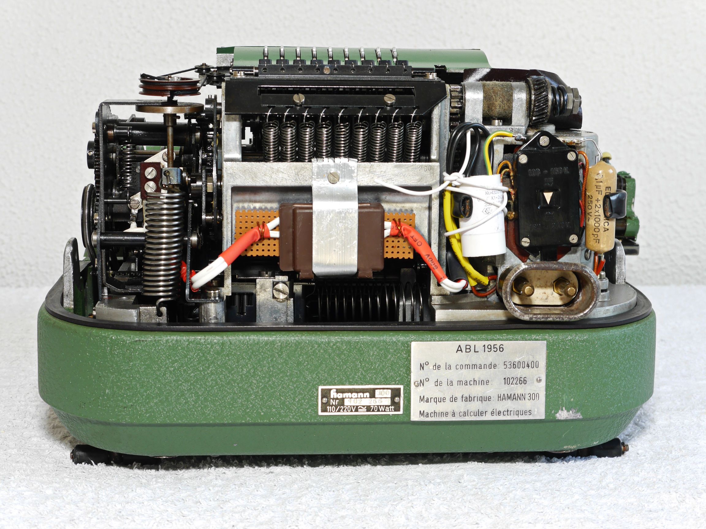
Spark suppression:
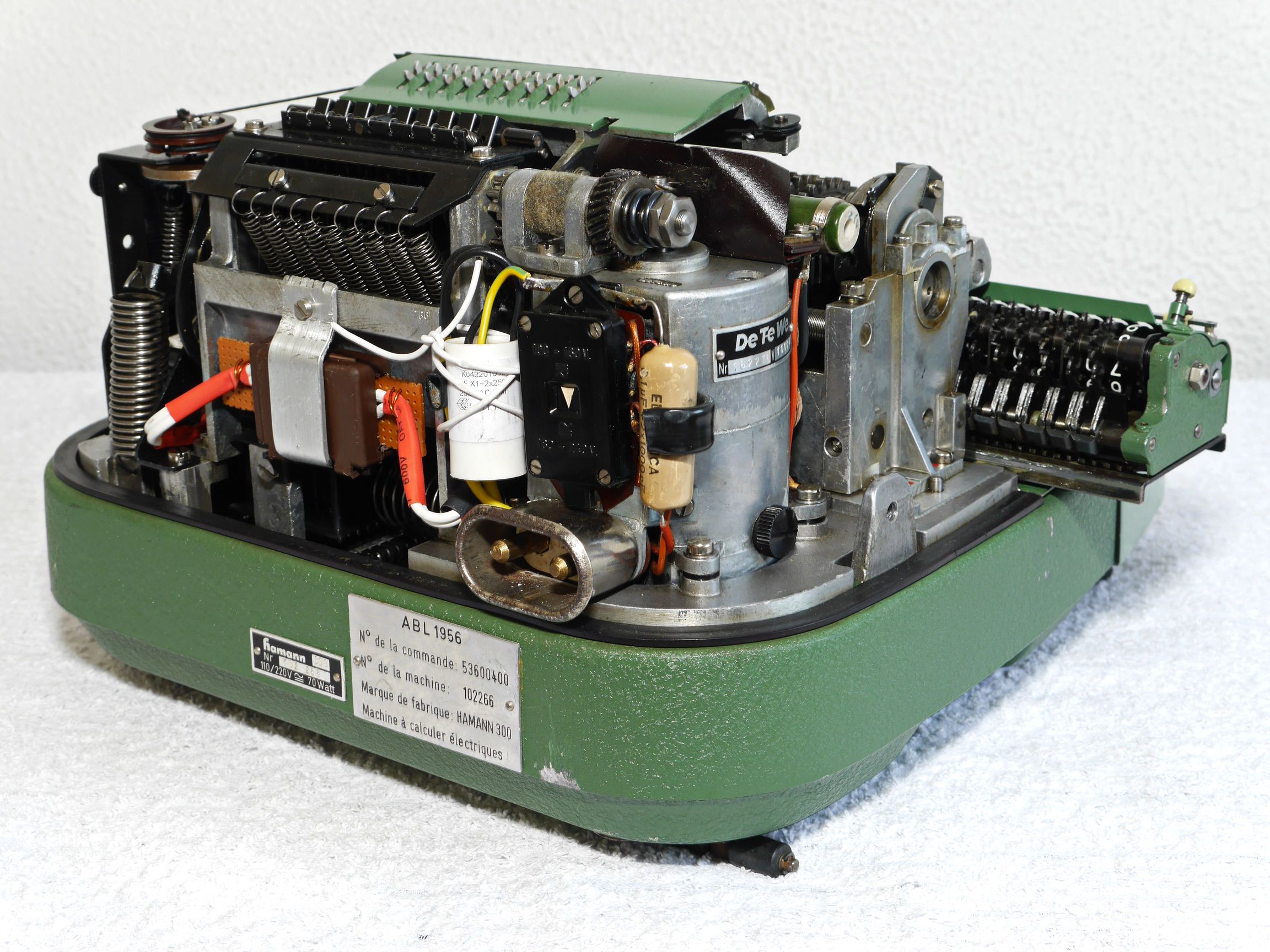
Many, perhaps most machines suffer from leaking or removed capacitors. In this machine they were removed. That’s not OK for those parts that take care of contact spark suppression. I tried to recover the original suppression circuitry.
If a leaking capacitor is “on power” constantly it will slowly heat up, leak a bit more, become heater and finally explode. If it does it may spread a lot of sticky, hard to remove dirt inside the machine.
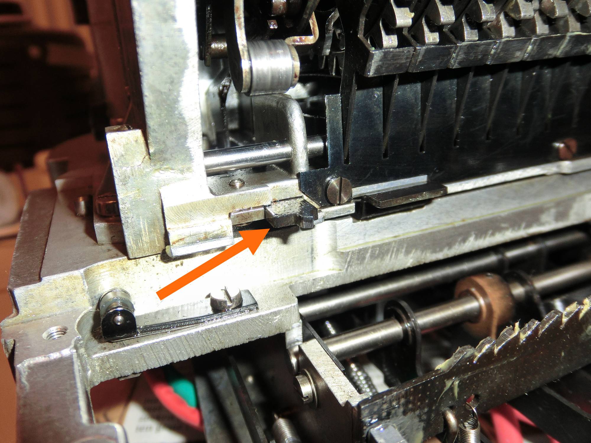
A: Carriage end stop
C: Carriage fixation while adding/subtracting
B: Counter half-way
D: Rotation 0-point

Motor speed control:
When the motor is removed from the main frame, the cover (E) of the speed control mechanism becomes visible. The ribbed black screw is used to adjust the speed. After taking off the cover the outside of the contacts (F) becomes visible.
(G) shows the centrifugal mechanism. (H) shows the hole which gives access to the speed control screw. It was about 220 rpm. Turning it to the right raises the speed. During maintenance I’ve set it to about 270 (not 350 to reduce mechanical stress). In the video it is 220 rpm.
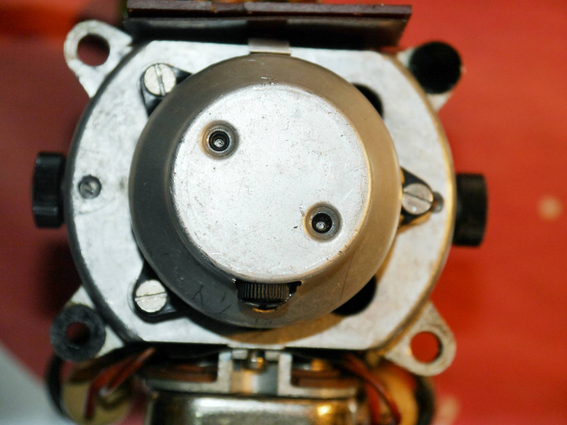
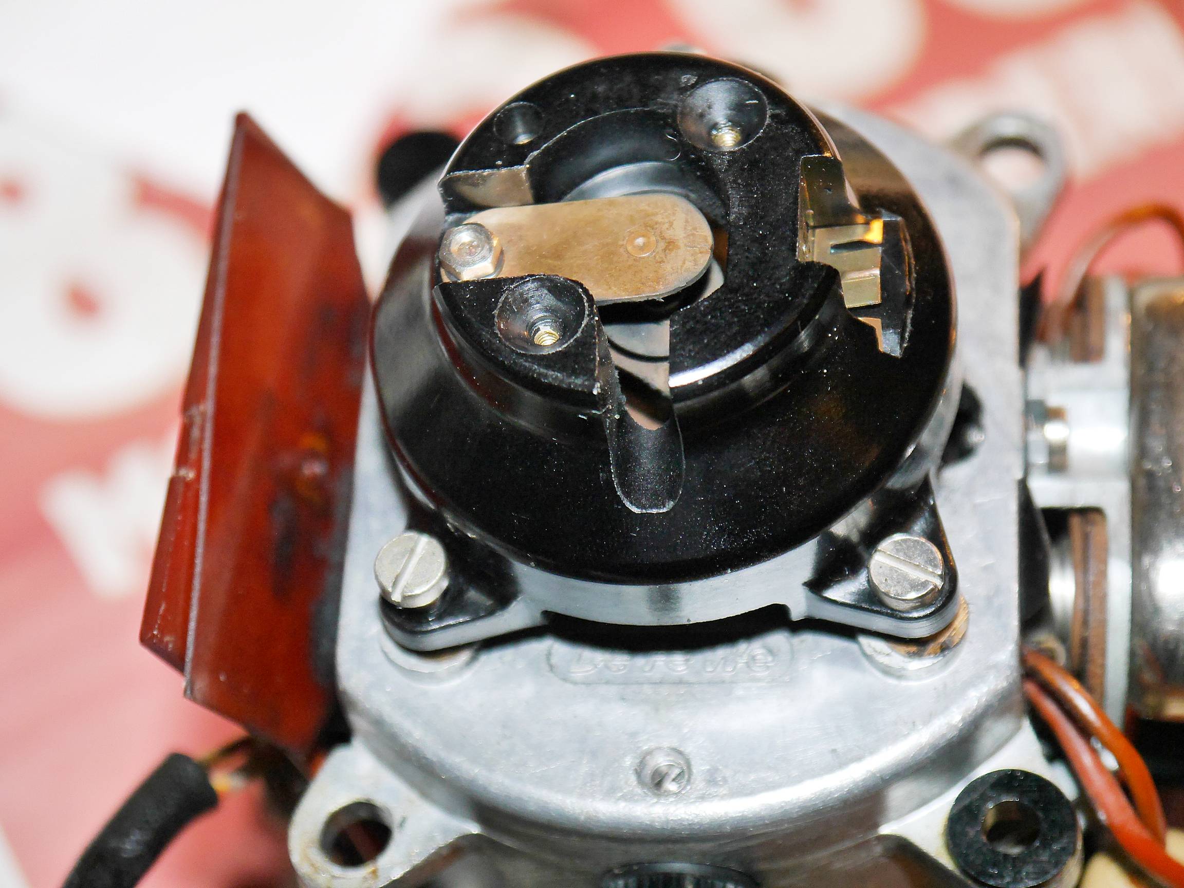
F: Contacts outside
G: Centrifugal mechanism
E: Cover
H: Speed control
| Mechanical Calculators |
| Electronic Calculators |
| Typewriters |